PROTOTYPE / FIT CHECKRevision 16 8 November 2026

Detachable camera modules

From CAD
to first print.

Everything the fabricator needs to inspect, print and fit the GoPro, Insta360 and adjustable industrial-camera mounts.

STL + STEP + DXF + drawings + hardware list
One ZIP. All three mount options.

IND / ADJUSTABLE CARRIERACTUAL CAD
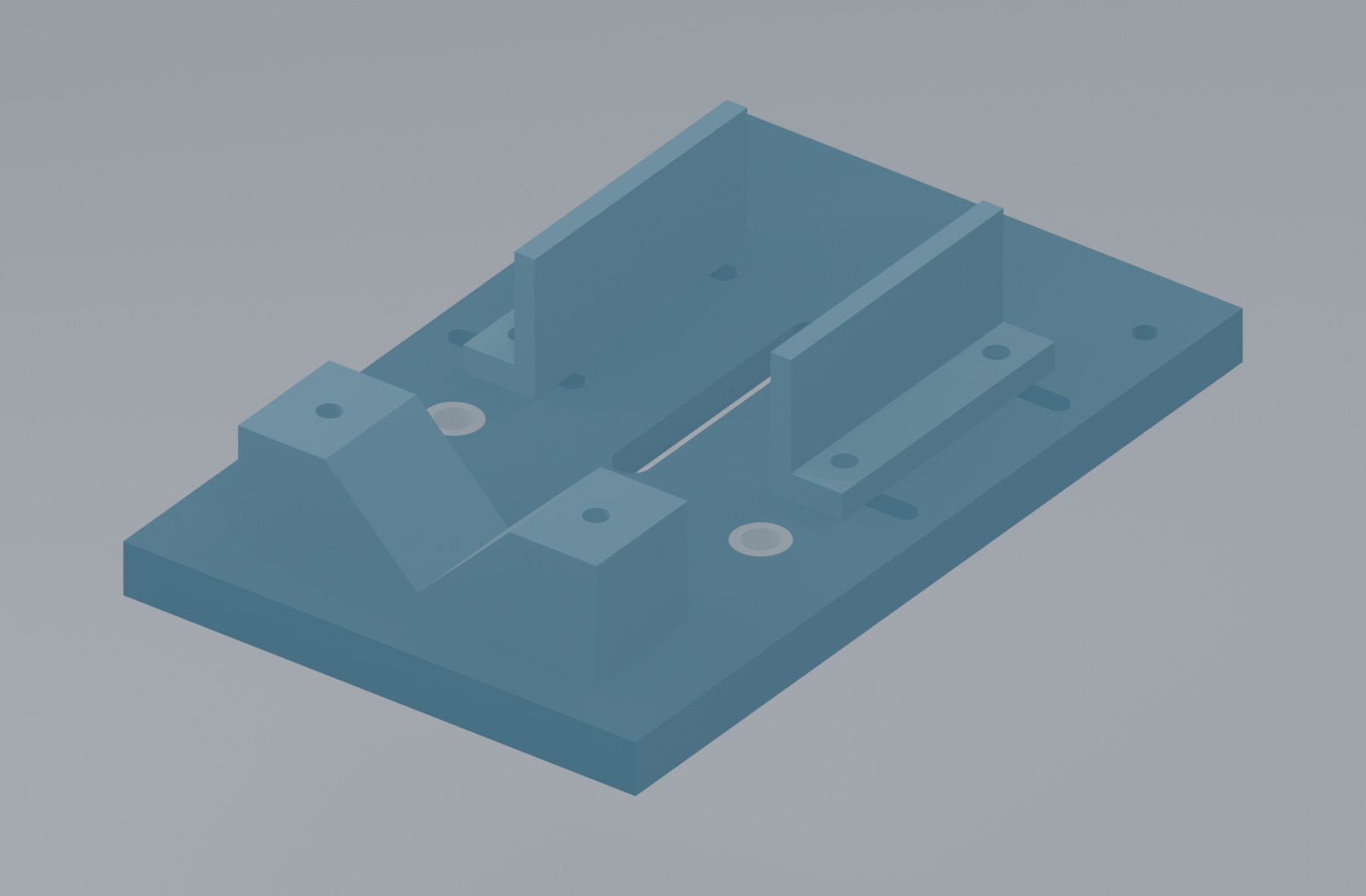
Printed industrial camera carrier with two sliding side jaws, lens saddle and four metal sleeves
01 Printed carrier02 Metal sleeves03 Sliding jaws
Custom mount body shown. Camera adapter and fasteners are separate.
3Camera families
10Parts in the first print batch
60 × 40 mmShared mounting-hole centres
STL / STEPPrint files + CAD solids

01 / Choose your module

One interface. Three mount options.

Each carrier detaches at the same four-hole connection. Print one of every required STL in the chosen camera folder.

GP3 required printed parts
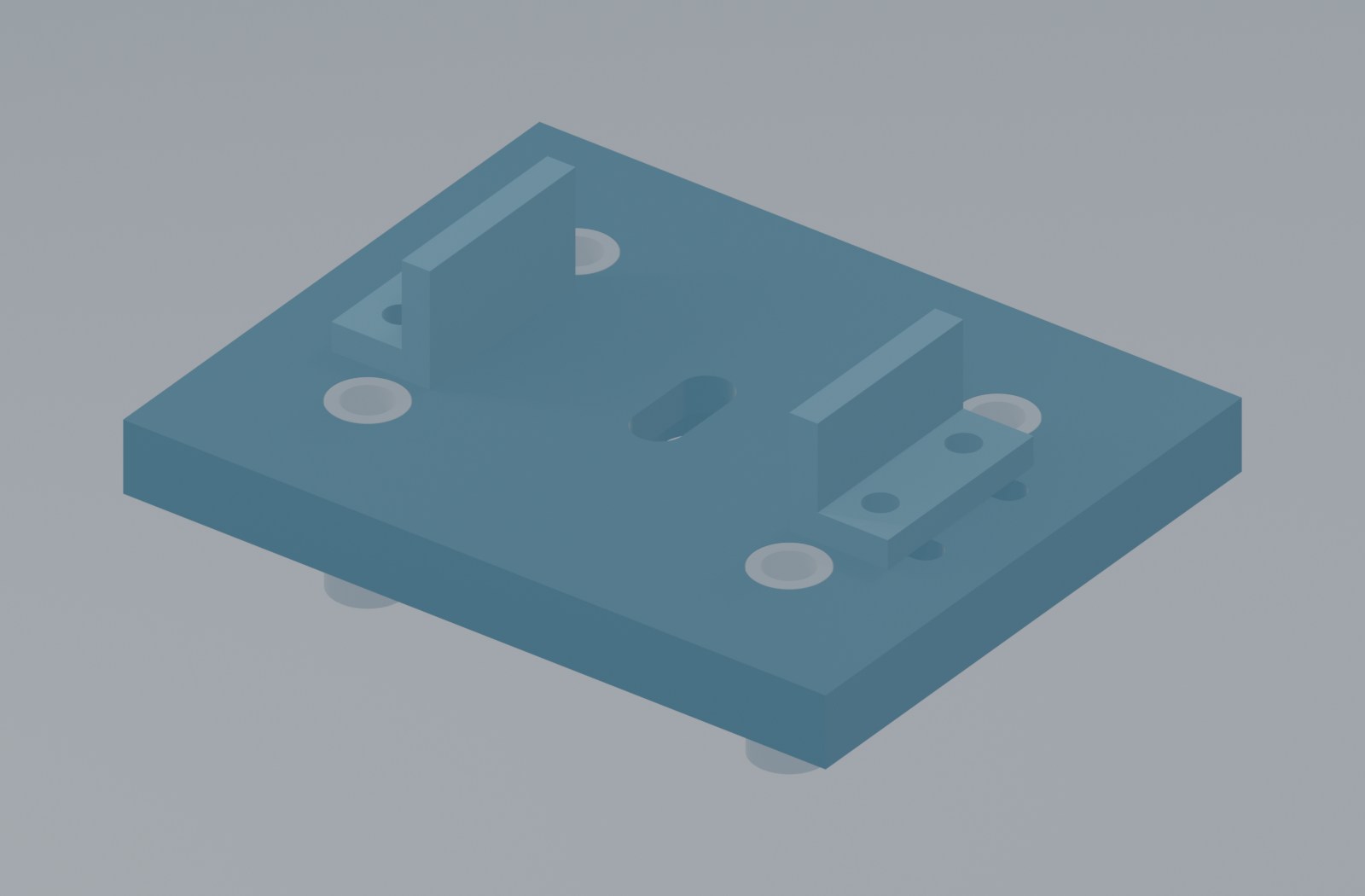
GoPro printed base with two adjustable low adapter keepers

GoPro MISSION 1 PRO

Printed base and two adjustable keepers for a purchased metal GoPro finger adapter.

Carrier
100 × 80 × 10 mm
Connection
Built-in camera fingers + metal adapter
Required print parts
  • GP02 · Sleeved base ×1
  • GP04 · Keeper ×1
  • GP05 · Opposite keeper ×1
Get STL set ↓
X63 required printed parts
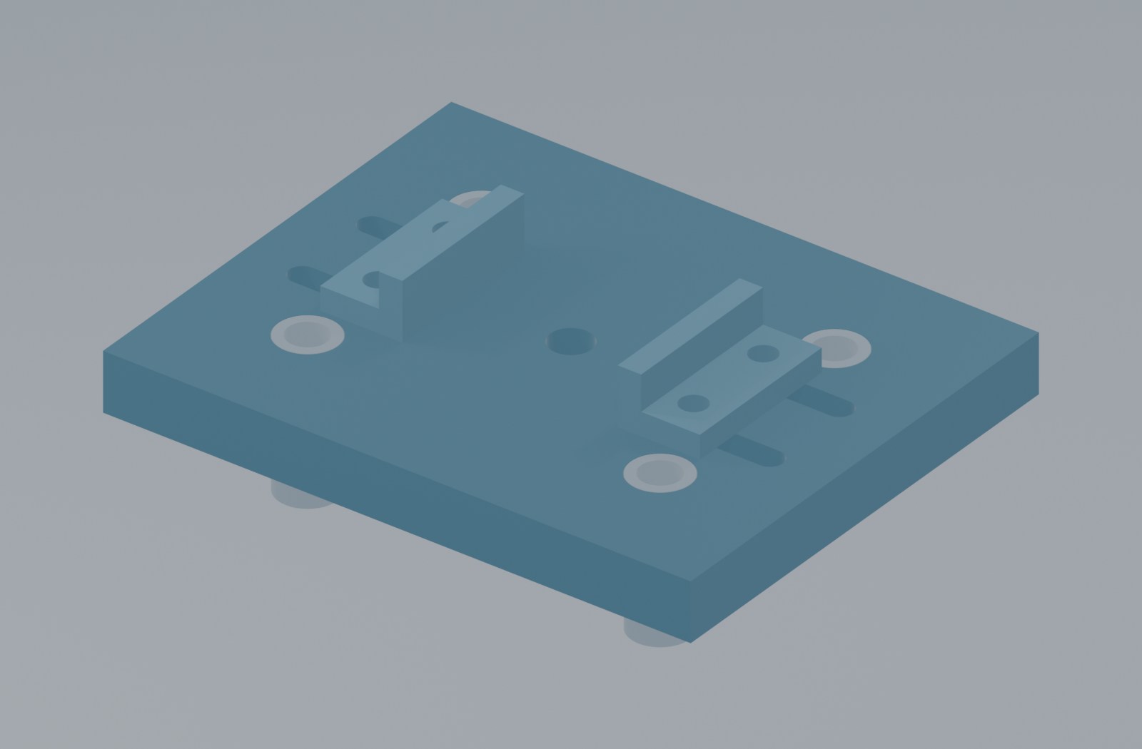
Insta360 X6 printed base with an adjustable lower locator on each side

Insta360 X6

Open lower-body locators and a bottom tripod-screw slot, keeping the lens area unenclosed.

Carrier
100 × 80 × 10 mm
Connection
Camera's bottom threaded socket
Required print parts
  • X602 · Sleeved base ×1
  • X604 · Locator ×1
  • X605 · Opposite locator ×1
Get STL set ↓
IND3 required + optional support
Industrial printed carrier and adjustable jaws with optional lens saddle

Adjustable industrial

Sliding side jaws and a slotted bed. Use the exact camera maker's body-to-tripod adapter.

Carrier
100 × 160 × 10 mm
Body-width range
24–68 mm with nominal 1 mm side pads
Required and optional parts
  • IND02 · Sleeved base ×1
  • IND04 · Jaw ×1
  • IND08 · Opposite jaw ×1
  • Optional: lens saddle, selected shims / riser
Get STL set ↓

The industrial module is adjustable within its stated range. Larger bodies, unusual feet, obstructed connectors or heavy lenses may need a different carrier. C-mount identifies a lens interface, not the camera-body attachment.

02 / Inspect the connection

Turn it. Separate it. Look underneath.

Actual CAD geometry. Rotate the mount and use the exploded view to see how its pieces connect.

Loading CAD…
Printed components Metal components
DRAG TO ORBIT · SCROLL TO ZOOM
Show component identifiers

03 / Give this to the rig fabricator

The shared
four-hole interface.

Four 6.6 mm through holes on 60 × 40 mm centres, for M6 clearance. Reference rig plate: 100 × 80 × 6 mm.

Printed sleeved carriers use 10.2 mm nominal sockets for metal sleeves with a 6.6 mm bore. These are different from the rig plate's bare 6.6 mm holes.

RIG-SIDE PLATE · mmSCHEMATIC
60 centres401004 × Ø6.6 THROUGH−30, +20+30, +20−30, −20+30, −20Centre (0, 0)

Coordinates shown relative to plate centre. See CSV for lower-left coordinates. PDF is not a scale drilling template.

04 / Print → fit → assemble

A clear first-batch sequence.

Download fabricator instructions ↓
  1. 01

    Print the dimensional coupon

    Start with IF02. Verify 100 × 80 mm overall size and 60 × 40 mm hole centres. Import STL as millimetres at 100% scale.

    Get coupon STL ↓
  2. 02

    Print one selected camera set

    One sleeved base and one locator of each hand: three printed parts per camera. The industrial base is the largest required part at 100 × 160 × 10 mm.

  3. 03

    Fit the actual camera and adapter

    Check safe screw engagement, socket position, contact surfaces, ports and doors. Use optional lens supports only after measuring the lens.

  4. 04

    Add the metal hardware

    Fit four compression sleeves and four 15 mm metal stand-offs. Fasten through the common M6 pattern, keeping screw ends and adjustment nuts clear.

  5. 05

    Record changes before more prints

    Mark the fit corrections. Keep the first batch for stationary testing; obtain material, retention and vibration validation before driving.

For the print shop

Use individual STL parts, not a fused assembly. Confirm bed size and plan support for the underside screw-head recesses. Printer-specific settings and G-code are not supplied. Choose material and process for the intended test.

05 / File library

The right file, without the guesswork.

STL for printing. STEP for CAD. DXF and PDF for the interface and fabrication details.

Loading file library…

File / purposeCameraFormatPrint qtyDownload
About SolidWorks

STEP files contain solid geometry. Open them in SolidWorks, check millimetres and save as native SLDPRT / SLDASM. Native feature history and mates are not included.

About optional parts

Plain-hole bases replace sleeved bases. Do not stack both. Lens-saddle shims and body risers are selected by actual measurements, not printed automatically.

06 / Materials & purchased interfaces

Parts the print
doesn't replace.

Use current manufacturer specifications and the actual hardware for the fit check. Final screw length depends on the measured stack and allowed camera-thread engagement.